With the computing power of the T12 processor and the data transfer capacity of the Pro II bus, the system sets new standards. Choose from a wide range of interfaces to find the perfect fit for your project. Benefit from synchronous data acquisition and output.
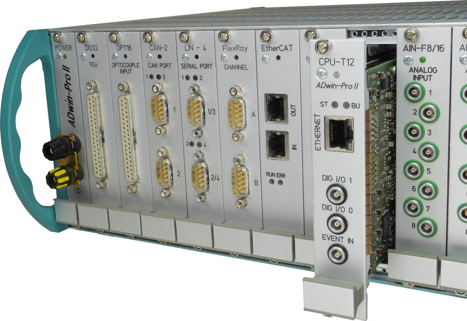
 Each additional bit doubles the quality of experimental measurements. That is why we are launching a new ADwin Pro II F card with fast 20-bit inputs – and with 16 channels per module simultaneously. This allows actual values to be recorded even more precisely, while even extremely fast controls gain in accuracy – without affecting system performance.
A typical application is quantum optical experiments with "optical tweezers", which require at least 32 analog and digital inoutputs for high-precision control of signal generators and laser shutters.
The new 20-bit input card offers a conversion time of 1 µs and can be seamlessly integrated into existing systems. Replacing a previous model is also easy to implement in terms of programming.
Details see "Analog Inputs with Fast-ADC", Tab "AIn-F-x/20"
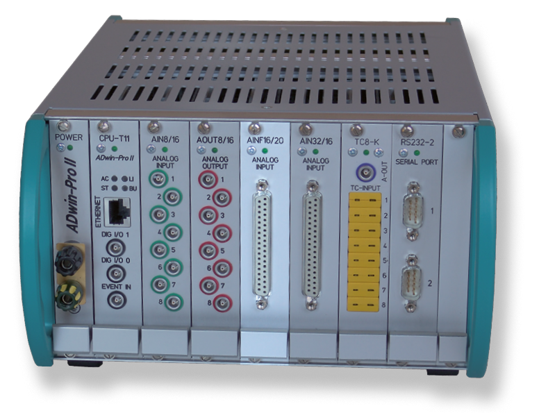
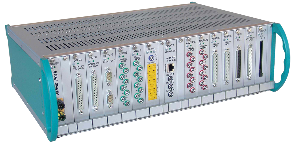
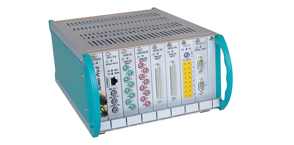
ADwin-Pro II is available in a variety of robust housings for a wide range of applications: as a desktop system for the laboratory (Standard), as a system for control cabinet mounting (BM), or as a system with DC power supply for mobile use (DC).
Up to 16 slots and a wide range of different modules provide the ideal, flexible basis for fast real-time applications.
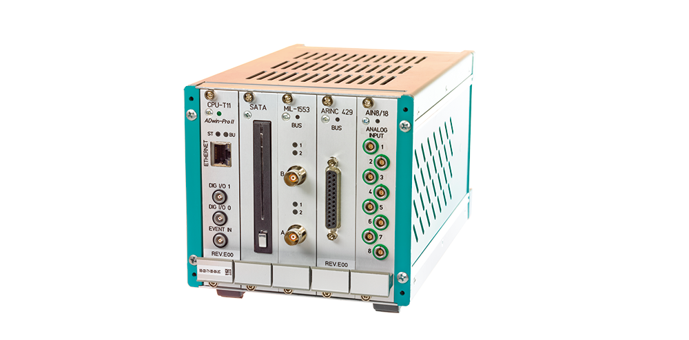


The analog input modules for ADwin-Pro II are the interfaces to your measuring devices, analog transducers, and amplifiers. They are ideal for solving fast and time-critical real-time tasks. Each analog signal is routed through its own ADC.
 Option: 16 channels, Lemo 1-pole
 Option: 4 channels, DSub
 Option: 4 channels, BNC
 Option: LEMO 2-pin
The analog input modules for ADwin-Pro II are the interfaces to your measuring devices, analog transducers, and amplifiers. They are ideal for solving fast and time-critical real-time tasks. The analog signals are routed to the ADC via a multiplexer.

| Plug | Without filter | Filter 5 kHz | Filter 50 kHz | Filter 10 kHz, ±30V |
|---|---|---|---|---|
| LEMO | AIn-8/18 | AIn-8/18-LP5 | – | AIn-8/18-LP-30V |
| LEMO, TiCo | – | – | AIn-8/18-LP50-TiCo | AIn-8/18-LP-30V-TiCo |
| DSub | AIn-8/18-D | AIn-8/18-LP5-D | – | AIn-8/18-LP-30V-D |
| DSub, TiCo | – | – | AIn-8/18-LP50-D-TiCo | AIn-8/18-LP-30V-D-TiCo |


The analog output modules for ADwin-Pro II are the interfaces to your measuring devices and actuators. They are ideal for solving fast and time-critical real-time tasks. Each analog signal is routed through its own DAC.
 Option: DSub, 4 channels
 Option: BNC, 8 channels


The module converts signals from Pt temperature sensors using analog-to-digital converters (ADC) and allows either the temperature or the applied voltage to be queried.
All settings are made via software. A sequence controller records the measured values and relieves the ADwin processor. The module can filter interference frequencies from the digital signals.
The module converts signals from common thermocouples and allows the temperature or the applied voltage to be queried (with and without cold junction compensation).
All settings are made via software. A sequence controller records the measured values and relieves the ADwin processor.
Are you still using modules from the ADwin-Pro I family? With the powerful T11 processor, you can work in a backward-compatible manner and use Pro I modules in parallel with Pro II modules.

Jäger Computergesteuerte
Messtechnik GmbH
Rheinstraße 2
D-64653 Lorsch

E-Mail: info@ADwin.de
Phone: +49 6251 9632-0